
4.3 Java 3D and the scenegraph
4.4 Elements of scenegraph design
4.7 Immediate mode vs. retained mode vs. mixed mode
Is a scenegraph appropriate for your application? If you choose to use a scenegraph for your application you should be able to sketch the required elements out on paper.
In this chapter, Ill introduce the concept of a scenegraph for modeling 3D scenes. Ill present several examples that can be used to guide the scenegraph design process for your application. Ill show you the benefits and drawbacks of using the Java 3D scenegraph along with comparative information for rendering in immediate mode and mixed mode. The possible elements of a Java 3D scenegraph are presented along with usage hints and tips.
Your applications 3D virtual world contains geometric objects with which the user interacts. In Java 3D this virtual world is called the VirtualUniverse, the top-level class that contains all the elements that you define within your virtual world. In addition, the VirtualUniverse contains nongeometric objects that control or influence the world. Lights are a good example of this type of object. In a 3D environment, one cannot see a Light, but one can see the effect of the Light within its zone of influence.
A concrete example helps to describe some of the details. Imagine a virtual world that models a Formula 1 Grand Prix race (figure 4.1). The model is a simplification of reality. It contains:
Taking a quick sum of the elements we see there are 1,473 objects in this VirtualUniverse. However, there are only 16 different types of objects. So, if you had the luxury of a team of 3D graphics artists and modelers, you could send the list away and a few weeks later receive 16 VRML format (for example) 3D graphics files. In fact, one might even define classes and subclasses, breaking the objects into cars, trees, people, billboards, bales, start light, racing circuit, and grass and hence require only eight classes. In this case the 3D graphics artists will produce a single F1 racecar model that can be customized (using color for example) to create the three subclasses McLaren, Williams, and Ferrari.
You should now be wondering how, with 1,473 distinct objects in your scenegraph and only eight classes of objects, you can organize the objects in your world so that you minimize memory overhead and rendering time but maximize programming flexibility.
You should also be aware that some of the objects within the world are dynamic:
Some of the objects are static:
It is important to note in this context that static means does not move relative to the circuit, or does not move relative to the grass area upon which the circuit sits. It does not mean that the items are static relative to the center of the universe or even (potentially) relative to the center of the Earth.
So, static and dynamic in this example have defined movement relationships between the items listed and the circuit. You should also therefore think about the spatial relationships between a class of items and all other classes of items. For example, the circuit never moves relative to the grass and maybe the straw bales are always situated 25 meters in front of a billboard; or you model groups of trees in which there was a fixed spatial relationship between the trees within each group.
Some of the objects have appearances that change:
Assume that you are using a low-level graphics API that can only render triangles, points, and lines at a given x, y, z coordinate.
Your primitive rendering loop might look like:
It should be obvious that this approach does not exploit much of the information about the structure of the world that you developed initially. The rendering API has no concept of an object and it has no concept of spatial (or otherwise) relationships between objects. This is analogous to sending your initial list of 1,473 objects to the graphics artists and making them do all the work.
What you need is a data structure that you can use both to describe the relationships between objects and exploit to optimize your rendering and memory requirements. Read on.
A scenegraph is a hierarchical data structure that captures the elements of spatial relationships between objects. Technically a scenegraph is a directed acyclic graph (DAG). Once you think and model an application hierarchically, the 3D graphics API is provided with a much richer set of information to use to optimize rendering. A scenegraph description also enables application developers to apply object-orientated (OO) principles such as abstraction and reuse to their designs.
In Java 3D, the scenegraph is encapsulated within the VirtualUniverse class. The scenegraph is composed of objects derived from the Node class. Every instance of the Node class has one parent Node. Additionally, the scenegraph contains objects derived from the Group class which encapsulates a collection of Node child objects. In this way a hierarchy of Group-derived objects can be created with Node-derived objects attached to the parent Group objects, as shown in figure 4.2.
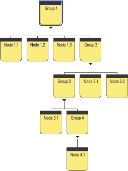
Groups with child Nodes. The parent-child relationships allow you to build a scenegraph hierarchy. Note that cycles are not permitted (e.g., Group 3 cannot also have Node 1.1 as a child); hence the scenegraph is a DAG
There are three basic classes of objects within the scenegraph:
Locale, BranchGroup, TransformGroup, ViewPlatform, Switch, and so forth. These are predominantly derived from Group and manage a collection of child objects.
Shape3D, Background, and so forth. These objects are derived from Leaf and define visible geometry within the applications virtual world.
Behaviors, Morph, Light, Sound, Clip, and so forth. These define application behavior and are typically not directly related to the geometry used within the application.
BranchGroup and TransformGroup are both Group nodes (i.e., they can contain child Nodes). A TransformGroup also contains translation, scaling, and rotation information that it applied to its child Nodes. The details of the nodes available in Java 3D are presented in later chapters.
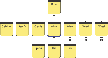
For example, consider how one might compose the scenegraph for the F1 car. The car can be roughly anatomized into seven parts (figure 4.3): four wheels, chassis, rear fin, and front stabilizer.
Groups
Each wheel is composed of spokes, a rim, and a tire. In this way the branch of the scenegraph that defines a wheelthat is, the Wheel Group and its three child Nodes, can be reused and duplicated to create the four wheels required for the F1 car.
The scenegraph also encodes a spatial relationship. When the F1 car is moved, its child Nodes are automatically also moved. For example, the stabilizer might be positioned three meters from the origin of the F1 car in the x directionthis spatial relationship will be preserved irrespective of the position of the F1 cars origin. If the wheel is rotated about its axis, the spokes, rim and tire will all be automatically rotated.
The scenegraph allows model complexity to be selectively specified. Just as you have chosen to create the Wheel from three subcomponents, you might choose to further decompose the chassis to introduce more detail into the model. You might have the opportunity to reuse scenegraph branchesperhaps other classes of vehicles at the race circuit require tires that are similar to the F1 tires? Perhaps you need to create piles of tires in the pit?
Various 3D graphics file formats (e.g., VRML) allow models to be created that are composed from subcomponents.
Figure 4.4 shows how the F1 car fits into the overall scenegraph for the F1 racing application.
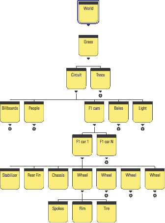
This scenegraph shown in figure 4.4 embodies the following relationships:
By designing the scenegraph with the spatial relationships in mind, scenegraph elements can be easily reused. Perhaps in the future the racetrack application will be expanded to contain two circuits with an animated transition sequence between them. The transition sequence will use a view from a helicopter flying between the circuits.
Youll need to reuse the circuit scenegraph branch and introduce a new element for the helicopter. Figure 4.5 shows how these elements might be introduced into the original scenegraph.
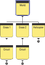
This formulation reuses the whole circuit branch of the scenegraph. The new circuit will have its own surrounding terrain and trees, as well as all the circuit geometry. Youll need to move the helicopter independently of the grass for each circuit, so the helicopter Group is added directly into the world Group. Moving the world will move the two circuits as well as the helicopter.
This section will cover additional scenegraph elements required by Java 3D to manage and render your scenegraph.
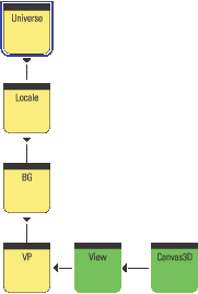
A VirtualUniverse contains at least one Locale object. A Locale defines a geographical region within your scenegraph. Locales are covered in depth in chapter 6.
In Java 3D there are two distinct branches within the scenegraph: scene and view. Up to now we have discussed only the high-level principles behind the scene side of the scenegraph. The scene branch contains the applications scenegraph elements, as discussed in the preceding examples. The view branch contains a ViewPlatform node and defines scaling, rotation, and translation information for the view. The view is responsible for rendering the scene side of the scenegraph. As shown in figure 4.6, the view attaches to a ViewPlatform and reads position and orientation information from the Nodes above the ViewPlatform on the view side of the scenegraph.
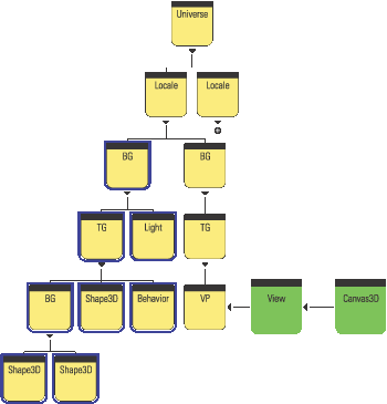
The view renders into its attached Canvas3D component. Canvas3D is a GUI component with an associated native windowing system window.
It is possible to have multiple ViewPlatforms in a scenegraph. Multiple ViewPlatforms allow you to define multiple points of view of your scene. By removing the view from a ViewPlatform and attaching it to a new ViewPlatform you can easily shift between predefined points of view.
It is also possible to have multiple views each rendering into multiple Canvas3Ds. For more on these advanced scenegraph features please refer to chapter 6.
An important property of a Node in the scenegraph is that it contains boundary (Bounds is the Java 3D class) information for the Node. The Bounds instance is typically a BoundingSphere or a BoundingBox object. These classes (derived from Bounds) define a volume of space within the 3D scene that encloses all the geometry and children of the Node. For the F1 car example this would mean that the Bounds for the F1 car Group node are such that they enclose the geometry for the stabilizer, rear fin, chassis, and four wheel Nodes. In turn, the Bounds for the wheel Group Node are such that they enclose the geometry for the spokes, rim, and tire Nodes.
Java 3D can exploit the hierarchical Bounds information to optimize many scenegraph operations, including rendering. For example, when the Renderer comes to render an F1 car, if it finds that the Bounds of the F1 car Group are outside the current view frustum the Renderer can immediately move on to the next car in the scene. The high-level visibility test on the F1 car Group has saved the Renderer from performing visibility tests on the child Nodes of the F1 car Group.
This implies another important property of a good scenegraph hierarchy: the structure of the scenegraph should provide as much Bounds information as possible to allow the Renderer to optimize rendering. As the scenegraph designer you should be cognizant of the potential Bounds of your scenegraph Nodes. From the full F1 race circuit example you could see that as you move down the scenegraph hierarchy the Bounds of the Groups and Nodes become smaller and smaller.
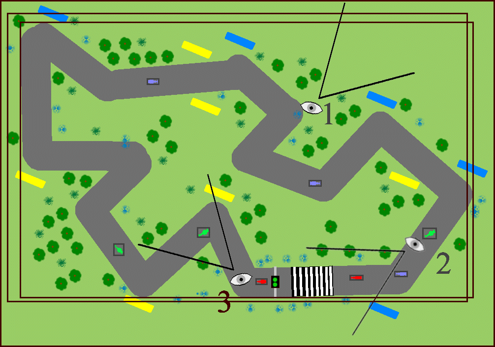
The Grass Group contains everything within the 3D scene, and as such must always be recursively processed by the Renderer. The Grass Group will be rendered irrespective of the users point of view of the scene. It would not matter whether the user was riding in-car with a point of view from one of drivers, was orbiting the circuit in a helicopter, or had a view from somewhere around the circuit. If the user can see the virtual world, the Renderer will process the grass Group. Figure 4.7 shows three sample points of view around the circuit.
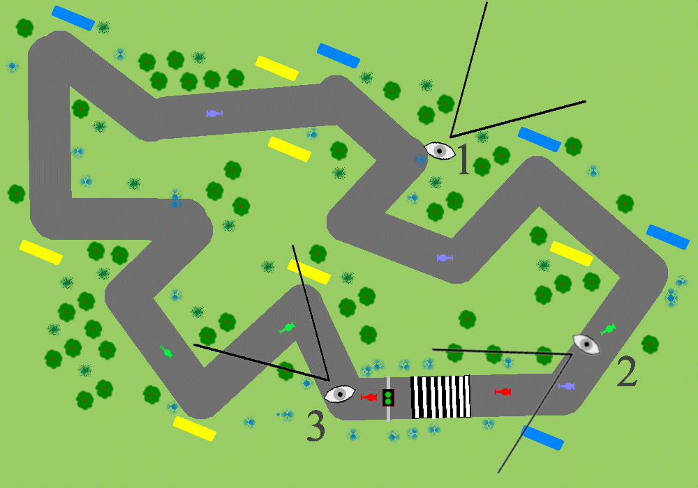
Bounds for the Grass Group enclose everything within the 3D scene. Three FOVs have been defined: #1 is a Marshals view, #2 is a McLaren drivers view, #3 is a Ferrari drivers view
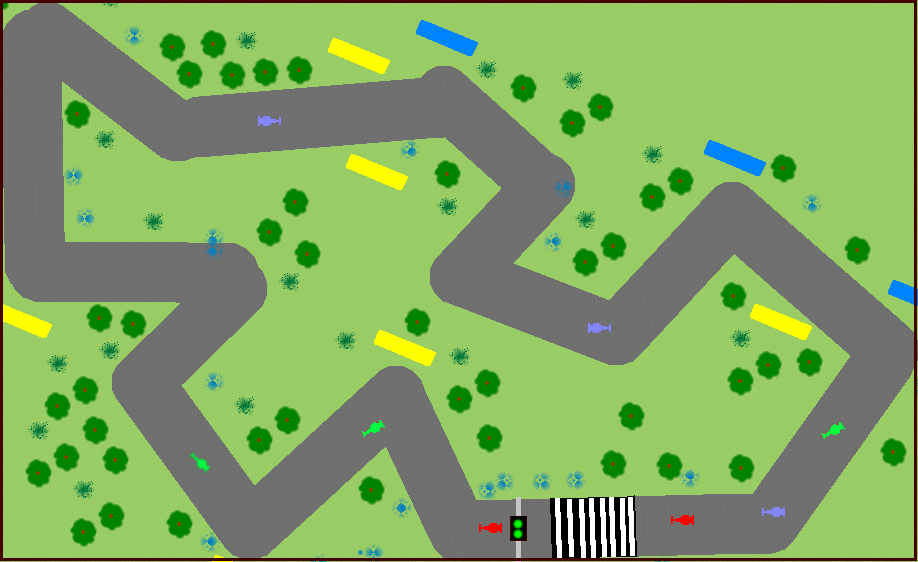
The trees Group (figure 4.8) contains all the trees within the scene. Since the trees are scattered across the terrain surrounding the race circuit the trees Group will have Bounds that are close to the size of the grass Group. The trees Group will also usually be processed by the scenegraph Renderer (as most points of view around the circuit will intersect trees). Conceivably the viewer of the scene could be positioned at the periphery of the circuit and facing away from the center of the circuit, such that their FOV falls outside of the Bounds of the trees Group. Note that FOV #1 is not such a case. Though viewer #1 cannot see any trees, his FOV does intersect the trees Groups Bounds object. Each of the trees within the Trees Group will have to be tested against FOV #1even though none of them actually intersect with FOV #1.

Bounds for the trees enclose all the trees within the 3D scene
The Circuit Group (figure 4.9) encloses all of the geometry that composes the circuit roadway. This is still a large Group and not significantly smaller than the overall grass Group. It is very unlikely that a viewer of the scene will not be able to view the circuit, which is the central feature of the application.
Bounds for the Circuit Group encloses the racing circuit
The F1 car Group (figure 4.10), on the other hand, merely has Bounds that enclose the geometry required for an individual F1 car (a meter by a few meters). It is very likely that a particular F1 car Group will not intersect a given FOV. It is highly unlikely that a single viewer will be able to see all of the F1 cars as they race around the circuit. For example
Groups
Group
Group

Bounds for the F1 car Group encloses the child Nodes that define the geometry for the F1 car
As there are 10 F1 car Groups in the scenegraph this represents a considerable saving.
The start light Group (figure 4.11) will be even smaller than the F1 car Group (less than a cubic meter). It will rarely intersect with a given FOV, even if we ride in the car with a driver. None of the FOVs defined on figure 4.7 can see the start light.
Bounds for the start light Group encloses just the child Nodes that define the geometry for the start light
Figure 4.12 shows bounding rectangles for five classes of objects in the racing circuit virtual world. The level of detail of objects within the world should reflect the theme of the application. For example, the grass around the circuit would probably be modeled as a simple rectangular height field with an applied texture image, while the F1 cars themselves would be complex 3D models composed from hundreds of vertices. On the other hand, if the application were a landscape design package the grass and trees may be represented using complex geometry. Some of the most challenging applications allow the user to control the application at several levels of detail, dynamically reapportioning the detail within the scene as appropriate. An excellent example of this is the game Black and White by Lionhead. The game allows the user to zoom out to control entire countries and to zoom in to view individual character animations and interactions.
Designing a good scenegraph structure may involve making trade-offs across several factors. The scenegraph should be easy to manipulate at runtime (you may want to dynamically attach and detach entire branches to switch them on or off) as well as easy to customize in the future. You may have to make compromises to get good performance to ensure that Java 3D can process your scenegraph efficiently.
Object orientation allows easy reuse of scenegraph branches. Ideally, each branch should define a component of the application that can be meaningfully used independently of the other scenegraph branches. You should imagine having to drop the scenegraph branch in question into another application.
This property is related to the goal of object orientation. If scenegraph branches can be reused within the scenegraph without modification of their appearance or relative position, then Java 3D can further optimize application performance by removing the duplicated branches and replacing them with a reference to a single, unique branch. Learn more about scenegraph compilation in chapter 5. In the F1 example, trees, billboards, and bales might all be good candidates for some form of compilation optimization.
A scenegraph branch should be able to have new child Nodes added to introduce new complexity into the scene, without disrupting other scenegraph branches.
By replacing child elements of a parent Group, you should be able to create new but related scenegraph branches.
Objects with large bounding volumes tend to imply often visible which generally implies performance critical. Do not make objects that are often visible (such as the trees in the Trees Group) of such high level of detail that they negatively impact application performance. Using high-detail models for the F1 cars themselves may be less critical as they have smaller Bounds and hence fewer of them are visible for most of the time. How you choose to apportion the detail within your scene will always be application/domain-specific or only domain specific, and may be related to the Bounds information of your scenegraph Nodes.
By now you should be aware of many of the advantages of using a scenegraph. Setting up the scenegraph hierarchy imposes a design rigor upon the application developer. Initially, particularly with scientific visualization applications, the scenegraph may seem unnecessarily restrictive, especially for developers from a low-level OpenGL or DirectX background. However, advanced planning and design will usually prove the utility of the scenegraph model, even for applications that do not initially appear to contain hierarchical graphical objects per se.
The scenegraph is a data structure. All the Nodes in it can also reference external data through the ScenegraphObject.setUserData method (discussed in chapter 8).
Scenegraph node Bounds play an important role in optimizing rendering and behavior scheduling.
Mouse object selection operations (picking) are automatically supported by the scenegraph.
Using Java 3D scenegraph behaviors allows scenegraph objects to be automatically rotated, transformed, and scaled using interactive user input, aligned relative to the FOV, animated, morphed, or controlled using a level of detail (LOD) behavior.
The Java 3D scenegraph supports basic collision detection between objects within the scenegraph.
The Java 3D scenegraph traversal, rendering, behavior, and collision detection systems are all thread aware and will make use of multiple threads.
Changing the position of a parent Node automatically changes the position of child Nodes accordingly. This is such an important and powerful concept that it is the subject of the next section and example.
Many 3D applications define a complex scenegraph hierarchy. An important function of the scenegraph is to enforce the geometric and spatial relationships that the scenegraph defines. Just as when the F1 car was moved its constituent parts were also moved. This principle is central to applications that require hierarchical control.
At the scenegraph level, the key to specifying relative positions for Nodes within the scenegraph is the TransformGroup Node. A TransformGroup encapsulates a Transform3D instance, which in turn encodes a 4 × 4 scaling, rotation, and translation matrix. The important principle is that a scenegraph Nodes rotation, scaling, and translation is always specified relative to its parent Nodes rotation, scaling, and translation.
To illustrate these principles, in this section Ill show you a Java 3D scenegraph to animate a model of a human arm (figure 4.13). Requirements of the model are:
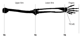
This model is obviously hierarchical. It would be most usual if when the elbow joint was rotated the lower arm and the fingers were not also displaced. An important principle of the scenegraph is that the position of a child Node only depends upon the positions of its parent Nodes. In other words, the position of the end of the little finger depends upon
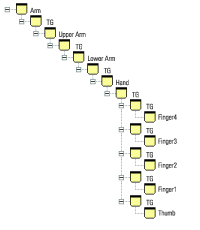
Converting the rotational requirements into a scenegraph hierarchical model produces a structure such as that in figure 4.14. Note that we have switched to a left-to-right tree representation of the scenegraph hierarchy to save space.
As with most things in life, things are not quite that simple. There are a few implementation-related issues that must also be resolved through the scenegraph structure. The scenegraph in figure 4.14 would be fine if you required just a static model of the human arm, but it would be nice to be able to illustrate the example by rotating the various joints to animate the model (as shown in figure 4.15). To simplify rotating the joints you must introduce another TransformGroup into the hierarchy for each limb to store the current joint rotation value. Two TransformGroups are thus required, one to store the length of the limb (i.e., the offset of the coordinate system of the next limb relative to the current limbs coordinate system) and one to store the joint rotation.

Unfortunately another minor implementation issue arises. The Cylinder geometric primitive that you are using to create the limbs in the model is created with 0,0,0 at the center of the cylinder. In other words, if you create a cylinder of length L, it will stretch from L/2 to L/2 in the y direction, with a given radius. We would like our cylinders to stretch from 0 to L in the y direction, so an additional TransformGroup is required to shift the cylinder upward by L/2 in the y direction.
When these refinements have been made, the scenegraph for the arm looks a little more complicated than our initial design but it still fulfills our rotation requirements for each joint. The completed scenegraph is illustrated in figure 4.16.
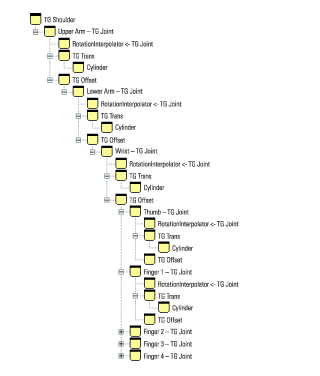
To verify the rotational requirements, you can walk up the scenegraph hierarchy from the end of Finger 1. Walking up the hierarchy will tell you what the position of the end of Finger 1 relies upon:
The rotational requirements have been satisfied, the scenegraph models the hierarchical structure of the human arm.
There are two slightly undesirable implications of the scenegraph as we have designed it. First, the length of the cylinder that we used for the geometry of the arm is unrelated to the length of the limb, inasmuch as the length of the Cylinder effects the next limb in the hierarchy. In this application, TG Offset and the length of the cylinder we created just happen to correspond. Second, the wrist and fingers are poorly modeled, as the fingers should be offset relative to one another. As modeled here the fingers all attach to the same location on the wrist.
Java 3D does not interact directly with system display hardware to produce the 3D rendering of a scene, but rather relies upon a lower level 3D graphics API: currently either OpenGL or DirectX. The designers of Java 3D have added several locations within the Java 3D rendering loop that application developers can hook into to directly render 3D primitives irrespective of the current scenegraph.
Using Java 3D in retained mode does not exploit these capabilities. This is usually the recommended and most common mode for Java 3D. The application developer defines the scenegraph for the application, passes it to Java 3D, and Java 3D is responsible for rendering the scene. Java 3D also coordinates and carries out a lot of the chores related to user interaction.
In complete contrast, using Java 3D in immediate mode does not exploit Java 3Ds scenegraph abilities at all, and the application developer assumes all responsibility for rendering and user interaction. Java 3D is merely being used as a cross-platform Java wrapper over the native low-level graphics API.
As its name implies, running Java 3D in mixed mode exploits some of each of the features of retained mode and some of the features of immediate mode. The application developer does define a scenegraph for some of the items in the scenegraph but retains responsibility for rendering certain 3D primitives that fall outside of the scenegraph structure.
Some might say that there is no pure immediate mode in Java 3D, as you must always create the View side of the scenegraph to activate the Java 3D rendering loop, within which the immediate mode code will execute. Syntactic quibbles aside, the ImmediateTest.java example renders an array of points in immediate mode and outputs the rendered FPS to standard output.
The minimal Java 3D scenegraph to activate the View rendering loop consists of a VirtualUniverse, a single Locale, and a BranchGroup with a single ViewPlatform child Node. A View is attached to the ViewPlatform and a Canvas3D is registered with the View (figure 4.17).
Canvas3D implements the immediate mode rendering callbacks
During the Java 3D rendering loop, the application developer is given several opportunities to prepare and render immediate mode information. The rendering loop calls four methods on the Canvas3D registered with the View. By overriding these callback methods, application-specific immediate mode rendering can be performed.
Canvas3D callback methods are
preRender: Allow you to prepare any data structures for rendering.
renderField: Can be overridden to perform the rendering.
postRender: Called when rendering is complete.
postSwap: Called once the rendered frame has been made visible to the user.
| From ImmediateTest.java |
//Define a custom Canvas3D that implements Immediate Mode rendering
//and outputs the FPS achieved.
class ImmediateCanvas3D extends Canvas3D
{
 private long               m_nRender = 0;
 private long               m_StartTime = 0;

 private static final int   nGridSize = 50;
 private static final int   m_kReportInterval = 50;

 private PointArray       m_PointArray = new PointArray( nGridSize *
  nGridSize, GeometryArray.COORDINATES );

 private Transform3D        m_t3d = new Transform3D();
 private float              m_rot = 0.0f;

 ImmediateCanvas3D(java.awt.GraphicsConfiguration
  graphicsConfiguration)
 {
  super( graphicsConfiguration );

  //create the PointArray that we will be rendering
  int nPoint = 0;

  for( int n = 0; n < nGridSize; n++ )
  {
   for( int i = 0; i < nGridSize; i++ )
   {
    Point3f point = new Point3f( n - nGridSize/2,
                                 i - nGridSize/2, 0.0f );
    m_PointArray.setCoordinate( nPoint++, point );
   }
  }
 }
![]()
The renderField method renders the actual PointArray that was created in the ImmediateCanvas3D constructor. In addition it tracks how many frames have been rendered and computes a running FPS count. Note that on the first frame the method adds lights and creates material attributes used to render the PointArray. The GraphicsContext3D used for rendering persists between rendering so take care not to add lights on every frame, or set material attributes unnecessarily.
At the heart of the renderField method are two calls: the first sets the Model transformation matrix for the GraphicsContext3D, the second calls the draw method on the GraphicsContext3D and passes the PointArray to be rendered:
 public void renderField( int fieldDesc )
 {
  super.renderField( fieldDesc );

  GraphicsContext3D g = getGraphicsContext3D();

  //first time initialization
  if( m_nRender == 0 )
  {
   //set the start time
   m_StartTime = System.currentTimeMillis();

   //add a light to the graphics context
   DirectionalLight light = new DirectionalLight( );
   light.setEnable( true );
   g.addLight( (Light) light );

   //create the material for the points
   Appearance a = new Appearance();
   Material mat = new Material();
   mat.setLightingEnable( true );
   mat.setAmbientColor( 0.5f, 1.0f, 1.0f );
   a.setMaterial( mat );
   a.setColoringAttributes(
    new ColoringAttributes( 1.0f, 0.5f, 0.5f,
                            ColoringAttributes.NICEST ) );

   //enlarge the points
   a.setPointAttributes( new PointAttributes( 4, true ) );

   //make the appearance current in the graphics context
   g.setAppearance( a );
  }

  //set the current transformation for the graphics context
  g.setModelTransform( m_t3d );

  //finally render the PointArray
  g.draw( m_PointArray );

  //calculate and display the frames per second for the
  //immediate mode rendering of the PointArray
  m_nRender++;

  if( (m_nRender % m_kReportInterval ) == 0 )
  {
   float fps = (float) 1000.0f /
               ((System.currentTimeMillis() - m_StartTime) /
               (float) m_kReportInterval);
   System.out.println( "FPS:\t" + fps );

   m_StartTime = System.currentTimeMillis();
  }
 }
The preRender method is called before every frame is rendered (though a call to renderField). This method sets up the Model transformation matrix that will eventually be used in the renderField call. By increasing the rotation about the y axis of the Model matrix, the PointArray is spun around its vertical axis. Note that the last call in preRender manually calls paint (not something that is usually advisable) to force the next frame to be drawn. In this way, you get a continuous frame-by-frame animation. Figure 4.18 shows a frame rendered by the ImmediateTest example.
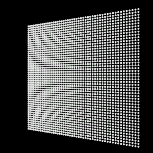
PointArray) has been rendered into the Canvas3D in immediate mode with a Model transformation applied to the GraphicsContext3D
 public void preRender()
 {
  super.preRender();

  //update the model transformation to rotate the PointArray about
  //the Y axis
  m_rot += 0.1;
  m_t3d.rotY( m_rot );

  //move the transform back so we can see the points
  m_t3d.setTranslation( new Vector3d( 0.0, 0.0, -20.0 ) );

  //scale the transformation down so we can see all of the points
  m_t3d.setScale( 0.3 );

  //force a paint (will call renderField)
  paint( getGraphics() );
 }
}
Rendering in mixed mode consists of nothing more than taking the ImmediateTest example and fleshing out the scenegraph to include geometry information. The MixedTest example adds the following Nodes to the scenegraph:
Canvas3D.
TransformGroup.
TransformGroup above.
Figure 4.19 shows a sample frame rendered by the MixedTest example.
PointArray) has been rendered into the Canvas3D in immediate mode while the ColorCube in the center was added to the scenegraph and rendered in retained mode. Also note that a background Node was used to color the background of the Canvas3D, also rendered in retained mode
| From MixedTest.java |
//Create a TransformGroup and attach a RotationInterpolator to spin
//the ColorCube about its vertical axis
TransformGroup objTrans = new TransformGroup();
objTrans.setCapability(TransformGroup.ALLOW_TRANSFORM_WRITE);
objTrans.setCapability(TransformGroup.ALLOW_TRANSFORM_READ);

BoundingSphere bounds =
 new BoundingSphere(new Point3d(0.0,0.0,0.0), 100.0);

Transform3D yAxis = new Transform3D();
Alpha rotationAlpha = new Alpha(-1, Alpha.INCREASING_ENABLE,
                                0, 0,
                                4000, 0, 0,
                                0, 0, 0);

RotationInterpolator rotator = new RotationInterpolator(
 rotationAlpha, objTrans, yAxis, 0.0f, (float) Math.PI*2.0f);
rotator.setSchedulingBounds(bounds);

//add the RotationInterpolator to its parent TransformGroup
objTrans.addChild(rotator);

//create the ColorCube and add to its parent TransformGroup
objTrans.addChild( new ColorCube() );>
![]()
Comparing figures 4.18 and 4.19, one might wonder why the grid of points (rendered in immediate mode) has become smaller. The answer is that the MixedTest example introduces a TransformGroup on the view side of the scenegraph. This TransformGroup shifts the position of the viewer backward relative to the scene so that the ColorCube is visible. The ImmediateTest example also sets a similar backward translation in the preRender method, before setting the Model matrix within the renderField method. The net effect is that the immediate mode PointArray has been translated backward twice relative to the vieweronce by the transformation on the View (retained) side of the scenegraph, and once explicitly in the immediate mode code. To render the immediate mode points irrespective of any transformation already applied by virtue of the view side of the scenegraph, one would have to calculate the view transformation, invert it, and multiply it by the desired Model transformation, all before applying it to the GraphicsContext3D. By inverting the view transformation, the effect of the transformation will be canceled.
Java 3D includes simple support to allow you to participate in the rendering cycle for each frame. The four Canvas3D methods allow you to perform fairly basic geometry rendering and frame capture. If you choose, these simple methods allow you to dispense with the scene side of the scenegraph and manage, transform, and render the geometry within your scene directly. Before rushing to a decision to use immediate mode, however, I urge you to examine the capabilities of retained mode closely. Java 3D has a strong bias toward retained mode and you could miss out on some important optimizations and features.
Mix and match from the pros and cons listed above. Decide acceptable application trade-offs between performance and ease of development and extensibility.
The scenegraph is the central data structure in Java 3D, and a good understanding of how to design an efficient scenegraphbalancing performance, reusability, and speed of developmentwill prove invaluable as you move on to design your application and read the chapters to come. You should experiment with the three examples covered in this chapter: ScenegraphTest, ImmediateTest, and MixedTest. By making changes, particularly to the scenegraph structure in the ScenegraphTest example, you will quickly be able to customize the examples to serve as simple prototypes for your own application.