6.2 View, ViewPlatform, and Locale
One of the fundamental choices you will have to make in your choice of VirtualUniverse configuration is whether to use the SimpleUniverse utility classes or to rely upon the lower level VirtualUniverse classes. By the end of this chapter you should understand the elements of the Java 3D scenegraph rendering model.
Essential elements of the Java 3D scenegraph are covered:
Locales
View model to the VirtualUniverse through the ViewPlatform
Views for rendering
SimpleUniverse utility classes
Views, Geometry, and PlatformGeometry for Avatars
The VirtualUniverse class contains the virtual world that an application developer populates with Geometry, Behaviors, Lights, and so forth. The VirtualUniverse consists of a collection of Locales. A Locale defines a geographical area within the VirtualUniverse and is anchored at a given 3D coordinate. A Locale uses 256-bit coordinates to specify the anchored x, y, and z position. The 256-bit coordinates are stored in a HiResCoord object and allow a Locale to be positioned within a virtual space the size of the known (physical) universe yet also maintain a precision of a Planck length (smaller than the size of a proton).
Most applications do not require more than one Locale; hence the SimpleUniverse class creates a VirtualUniverse instance with a single Locale. SimpleUniverse is derived from VirtualUniverse and is covered in detail in chapter 3. The default constructor for a Locale positions the Locale at the origin of the VirtualUniverse. Within a Locale, doubles or floats are used to specify the positions of objects. If a double is large enough to represent the positions of all the objects within your scene accurately, then a single Locale should be sufficient.
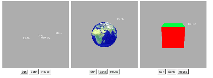
However, imagine a scenario: your application is to model parts of the galaxy. The model is to contain the planets orbiting the Sun. On the Earth, the model contains a geometry object a few meters across to represent a house. All the objects in the model are to be created to scale.
How would one go about building such a model for the viewer to be able to switch between three different viewing modes?
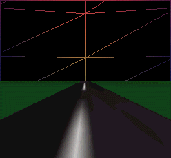
Locales were designed to handle applications such as that just described. The HiResCoordTest example implements the application shown in figure 6.1. Creating multiple Locales is a fairly lengthy process, so the whole example cannot be included here.
Locales defined in HiResCoordTest.java
The first problem encountered is how to specify the location of a Locale.
| From HiResCoordTest.java |
protected Locale createLocaleEarth( VirtualUniverse u )
{
 int[] xPos = { 0, 0, 0, 0, 0, 0, 0, 0 };
 int[] yPos = { 0, 0, 0, 0, 0, 0, 0, 0 };
 int[] zPos = { 0, 0, 0, 1, 0, 0, 0, 0 };

 HiResCoord hiResCoord = new HiResCoord( xPos, yPos, zPos );
 return new Locale( u, hiResCoord );
}
![]()
A HiResCoord is created using three 8-element integer arrays. An int is 32 bits, so 8 * 32 = 256 bits.
| NOTE |
The integer at index 0 contains the most significant bit, while the integer at index 7 contains the least significant bit. The decimal point is defined to lie between indexes 3 and 4, that is, 0x0 0x0 0x0 0x0 . 0x0 0x0 0x0 0x0 The 8-element integer array to specify a coordinate can be considered an 8-digit number in base 232. The numbers that can be expressed by such an entity are mind-boggling, but table 6.1 (from the API specification) can be used to get you into the right ballpark for the quantity you are trying to express. |
| 2n Meters | Units |
|---|---|
| 87.29 | Universe (20 billion light-years) |
| 69.68 | Galaxy (100,000 light-years) |
| 53.07 | Light-year |
| 43.43 | Solar system diameter |
| 23.60 | Earth diameter |
| 10.65 | Mile |
| 9.97 | Kilometer |
| 0.00 | Meter |
| 19.93 | Micron |
| 33.22 | Angstrom |
| 115.57 | Planck length |
For example, to specify a distance in light-years (9,460 billion kilometers), find from table 6.1 that 253.07 is equal to 9,460 billion kilometers. That is, a 1 at the 53rd bit position will be approximately one light-year. When mapped into the integer array, the 53rd bit is located within the integer at index 3 53/32 = 2. It is the 21st bit (53 32) within the third integer of the array. The number 221 equals 0x200000, so setting the integer at index 2 of the integer array to 0x200000 will create a HiResCoord instance that stores approximately a light-year.
The integer at index 3 is defined to store meters, so simply setting the integer at index 3 will define a HiResCoord in meters. Conversely, the 20th bit to the right of the decimal point position is approximately a micron.
A useful exercise would be to develop a Java class that returned a HiResCoord for quantities expressed in the various units shown in table 6.1.
 //creates a Locale that is positioned (232 + 5) meters
 //away from the origin in the +Z direction.
 int[] xPos = { 0, 0, 0, 0, 0, 0, 0, 0 };
 int[] yPos = { 0, 0, 0, 0, 0, 0, 0, 0 };
 int[] zPos = { 0, 0, 1, 5, 0, 0, 0, 0 };

 HiResCoord hiResCoord = new HiResCoord( xPos, yPos, zPos );
Once a Locale has been created and positioned, it can be populated with geometry by attaching a BranchGroup containing scenegraph elements:
//create the Universe
m_Universe = new VirtualUniverse();

//create the position for the Locale
int[] xPos = { 0, 0, 0, 0, 0, 0, 0, 0 };
int[] yPos = { 0, 0, 0, 0, 0, 0, 0, 0 };
int[] zPos = { 0, 0, 1, 5, 0, 0, 0, 0 };
HiResCoord hiResCoord = new HiResCoord( xPos, yPos, zPos );

//create the Locale and attach to the VirtualUniverse
Locale locale = new Locale( u, hiResCoord );

//create the BranchGroup containing the Geometry for the scene
BranchGroup sceneBranchGroup = createSceneBranchGroup();
sceneBranchGroup.compile();

//add the scene BranchGroup to the Locale
locale.addBranchGraph( sceneBranchGroup );
Note that this code will not yet make the geometry visible until a View and a ViewPlatform are created. This is the subject of the next section.
Now that a Locale has been created and populated with geometry, Java 3D must be instructed to render the Locale. The key to Java 3D rendering is the View class which attaches to the ViewPlatform instance that is within the scenegraph. The View controls Java 3D rendering and must have an attached Canvas3D component to render into. Multiple Canvas3D instances can be attached to the View, allowing multiple (identical) copies of the View to be rendered simultaneously.
| CLIPPING PLANES |
The clipping planes for the View control how much of the scene is rendered. In the example, the front plane is 10 meters from the viewer, while the back clipping plane is 110 meters from the viewer. However, since the viewer has been moved back 20 meters from the origin, the scene will be rendered from 10 to +90 in the Z direction. Note that one cannot set arbitrary clipping planes. The clipping planes have a physical significance in that they define a view frustum. The view frustum defines the pyramidal volume of 3D space that is rendered. |
The ViewPlatform is a simple Java 3D Leaf Node and can be added to the Locale as shown by the Java3dApplet code:
| Based on Java3dApplet.java |
//create the ViewPlatform BranchGroup
BranchGroup vpBranchGroup = new BranchGroup();

//create a TransformGroup to scale the ViewPlatform
//(and hence View)
TransformGroup tg = new TransformGroup();

//create the ViewPlatform
ViewPlatform vp = new ViewPlatform();
vp.setViewAttachPolicy( View.RELATIVE_TO_FIELD_OF_VIEW );

//attach the ViewPlatform to the TransformGroup
tg.addChild( vp );

//attach the TransformGroup to the BranchGroup
vpBranchGroup.addChild( tg );

//finally, add the ViewPlatform BranchGroup to the Locale
locale.addBranchGraph( vpBranchGroup );
![]()
Note that the TransformGroup created just before the ViewPlatform can be used to scale, translate, or rotate the scene rendered by the View attached to the ViewPlatform. For example:
//Move the camera BACK a little. Note that Transformation
//matrices above the ViewPlatform are inverted by the View
//renderer prior to rendering. By moving the camera back 20
//meters, you can see geometry objects that are positioned at 0,0,0.
Transform3D t3d = new Transform3D();
t3d.setTranslation( new Vector3d( 0.0, 0.0, 20.0 ) );
tg.setTransform( t3d );
Now we need to create the View object itself and attach it to the ViewPlatform that was added to the scenegraph.
//create the View object
View view = new View();
//create the PhysicalBody and PhysicalEnvironment for the View
//and attach to the View
PhysicalBody pb = new PhysicalBody();
PhysicalEnvironment pe = new PhysicalEnvironment();
view.setPhysicalEnvironment( pe );
view.setPhysicalBody( pb );

//attach the View to the ViewPlatform
view.attachViewPlatform( vp );

//set the near and far clipping planes for the View
view.setBackClipDistance( 110 );
view.setFrontClipDistance( 10 );
Finally, create a Canvas3D component (an AWT object) and add it to the Views list of Canvases to be rendered into.
//create the Canvas3D that the View will render into.
//get the graphics capabilities of the system and create
//the best Canvas3D possible.
GraphicsConfigTemplate3D gc3D = new GraphicsConfigTemplate3D();
gc3D.setSceneAntialiasing( GraphicsConfigTemplate.PREFERRED );
GraphicsDevice gd[] = GraphicsEnvironment.
 getLocalGraphicsEnvironment().getScreenDevices();

Canvas3D c3d = new Canvas3D( gd[0].getBestConfiguration( gc3D ) );

//set the size of the Canvas3D
c3d.setSize( 512, 512 );

//add the Canvas3D to the View so that it is rendered into
view.addCanvas3D( c3d );

//add the Canvas3D component to a parent AWT or Swing Panel
add( c3d );
To simplify creating the View side of the scenegraph, Sun has provided the SimpleUniverse class (figure 6.2). SimpleUniverse is defined in the com.sun.j3d.utils package and as such should not be considered part of the core Java 3D API. The SimpleUniverse class hides some of the complexity of manually defining the View side of the scenegraph at the expense of the flexibility of using the core API classes only.
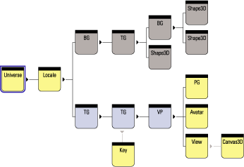
SimpleUniverse class encapsulates the details of the view side of the scenegraph (lower branch). The ViewingPlatform has been highlighted and contains a MultiTransformGroup composed of two TransformGroups. Attached to the ViewPlatform are a PlatformGeometry Group and a ViewerAvatar Group. By attaching a Key behavior to one of the TransformGroups in the MultiTransformGroup, the View, PlatformGeometry, and ViewerAvatar can all be moved simultaneously and rendered into the Canvas3D attached to the view
SimpleUniverse is a bit of a misnomer since the class is anything but simple, and this can cause initial confusion because of the plethora of support classes that it relies upon. SimpleUniverse introduces five new (non-core-API) classes:
Viewer, a container class that keeps references to the following:
ViewerAvatar, a representation of the viewer of the scene.
Canvas3D, used for rendering the scene.
Frame contains the Canvas3D used for rendering.
PhysicalBody references the views PhysicalBody.
PhysicalEnvironment references the views PhysicalEnvironment.
ViewingPlatform (extends BranchGroup) helps set up the View side of the scenegraph by creating a hierarchy of TransformGroups above the ViewPlatform where the view is attached to the scenegraph. The hierarchy of TransformGroups is encapsulated in a MultiTransformGroup. In this way a series of transformations can be applied to the view irrespective of transformations that are applied on the geometry side of the scenegraph.
ViewerAvatar (extends BranchGroup) contains the geometry used to render the viewers virtual self in the virtual environment.
MultiTransformGroup is a simple encapsulation of a Vector of TransformGroups.
PlatformGeometry (extends BranchGroup) contains the geometry associated with the viewers ViewingPlatform. For example, in a multiplayer gaming scenario, each player might be able to drive one of several vehicles. A ViewingPlatform would represent each vehicle in the scenegraph, and the geometry for the vehicle would be attached to the ViewingPlatform. The player would be represented by geometry attached to the ViewerAvatar, which in turn would govern another players view of the player, while the ViewingPlatform would contain the geometry to describe the internal characteristics of the vehicle the player was riding in. By attaching the view to different ViewingPlatforms, the player can move between vehicles.
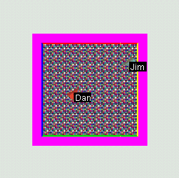
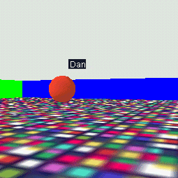
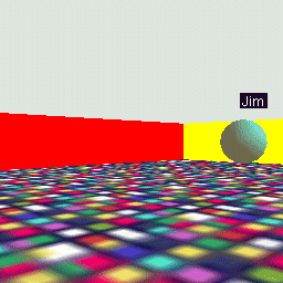
In the PlatformTest example, two avatars (Dan and Jim) and three views are created: overhead, Dans, and Jims (figures 6.36.5). Each Avatar is assigned ViewerAvatar geometry (a simple Cone pointing in the direction of view) and PlatformGeometry (a text label to identify the avatar).
The example is too lengthy to be included in its entirety but some illustrative excerpts have been extracted:
| From PlatformTest.java |
//This method creates the SimpleUniverse View and ViewPlatform
//scenegraph elements to create an avatar that has an associated
//Canvas3D for rendering, a PlatformGeometry, ViewerAvatar, and a
//KeyNavigator to allow movement of the ViewerAvatar with the
//keyboard.
ViewingPlatform createViewer( Canvas3D c, String szName,
  Color3f objColor, double x, double z )
{
 //create a Viewer and attach to its canvas. A Canvas3D can
 //only be attached to a single Viewer.
 Viewer viewer2 = new Viewer( c );

 //create a ViewingPlatform with 1 TransformGroup above the
 //ViewPlatform
 ViewingPlatform vp2 = new ViewingPlatform( 1 );

 //create and assign the PlatformGeometry to the Viewer
 vp2.setPlatformGeometry( createPlatformGeometry( szName ) );

 //create and assign the ViewerAvatar to the Viewer
 viewer2.setAvatar( createViewerAvatar( szName, objColor ) );

 //set the initial position for the Viewer
 Transform3D t3d = new Transform3D();
 t3d.setTranslation( new Vector3d( x, 0, z ) );
 vp2.getViewPlatformTransform().setTransform( t3d );

 //set capabilities on the TransformGroup so that the
 //KeyNavigatorBehavior can modify the Viewer's position
 vp2.getViewPlatformTransform().setCapability(
  TransformGroup.ALLOW_TRANSFORM_WRITE );
 vp2.getViewPlatformTransform().setCapability(
  TransformGroup.ALLOW_TRANSFORM_READ );

 //attach a navigation behavior to the position of the viewer
 KeyNavigatorBehavior key = new KeyNavigatorBehavior(
  vp2.getViewPlatformTransform() );
 key.setSchedulingBounds( m_Bounds );
 key.setEnable( false );

 //add the KeyNavigatorBehavior to the ViewingPlatform
 vp2.addChild( key );

 //set the ViewingPlatform for the Viewer
 viewer2.setViewingPlatform( vp2 );

 return vp2;
}

//creates and positions a simple Cone to represent the Viewer.
//The Cone is aligned and scaled such that it is similar to a 3D
//"turtle".
ViewerAvatar createViewerAvatar( String szText, Color3f objColor )
{
 ViewerAvatar viewerAvatar = new ViewerAvatar();

 //rotate the Cone so that it is lying down and the sharp end
 //is pointed toward the Viewer's field of view.
 TransformGroup tg = new TransformGroup();
 Transform3D t3d = new Transform3D();
 t3d.setEuler( new Vector3d( Math.PI / 2.0, Math.PI, 0 ) );
 tg.setTransform( t3d );

 //create appearance and material for the Cone
 Appearance app = new Appearance();
 Color3f black = new Color3f(0.4f, 0.2f, 0.1f);
 app.setMaterial(new Material(objColor, black, objColor,
   black, 90.0f));

 //create the Primitive and add to the parent BranchGroup
 tg.addChild( new Cone( 1, 3, Primitive.GENERATE_NORMALS, app ) );
 viewerAvatar.addChild( tg );

 return viewerAvatar;
}

//create a simple Raster text label used to help identify
//the viewer.
PlatformGeometry createPlatformGeometry( String szText )
{
 PlatformGeometry pg = new PlatformGeometry();
 pg.addChild( createLabel( szText, 0f, 2f, 0f ) );

 return pg;
}

//creates a simple Raster text label (similar to Text2D)
private Shape3D createLabel( String szText, float x,
  float y, float z )
{
 BufferedImage bufferedImage = new BufferedImage( 25, 14,
  BufferedImage.TYPE_INT_RGB );
 Graphics g = bufferedImage.getGraphics();
 g.setColor( Color.white );
 g.drawString( szText, 2, 12 );

 ImageComponent2D imageComponent2D = new ImageComponent2D(
  ImageComponent2D.FORMAT_RGB, bufferedImage );

 //create the Raster for the image
 javax.media.j3d.Raster renderRaster = new javax.media.j3d.Raster(
              new Point3f( x, y, z ),
              javax.media.j3d.Raster.RASTER_COLOR,
              0, 0,
              bufferedImage.getWidth(),
              bufferedImage.getHeight(),
              imageComponent2D,
              null );

 return new Shape3D( renderRaster );
}
![]()
The SimpleUniverse class allows you to attach geometry to the viewer of your 3D scene. There are two methods of attaching viewer geometry using the SimpleUniverse class: ViewingPlatform.setPlatformGeometry or Viewer.setAvatar. The ViewingPlatform can be accessed from the SimpleUniverse by calling getViewingPlatform or calling getViewer to access the Viewer object. There does not seem to be any difference between these two methods.
There is nothing magical about the geometry that represents the viewer; it may be easier, and more consistent in your application, to represent the viewer using a separate BranchGroup attached to the root of your scenegraph. SimpleUniverse is defined in the Java 3D utilities package (com.sun.java.j3d.utils) along with the Viewer, ViewerAvatar, and ViewingPlatform classes. These classes are merely defined for convenience; it may be safer to use the core Java 3D scenegraph management classes.
That said, here is a short example of using setPlatformGeometry to assign geometry for the Viewer; the output is shown in figures 6.66.7.
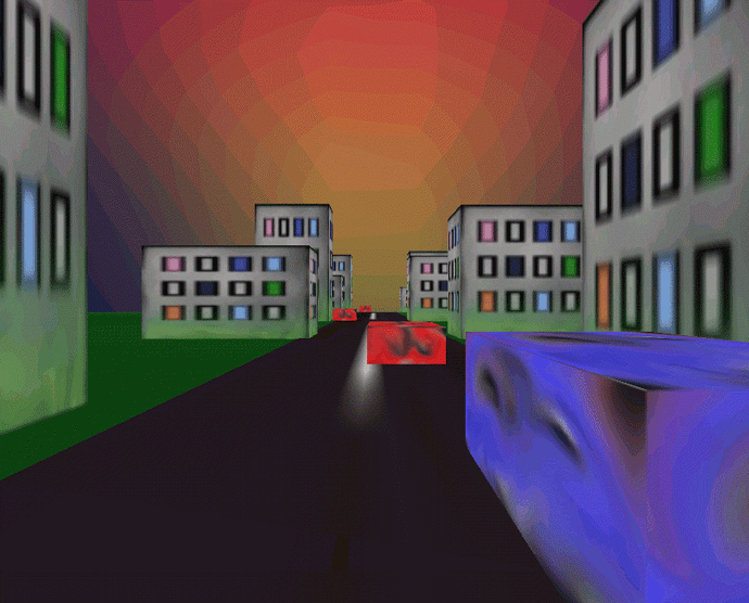
AvatarTest. The viewers avatar is the large cube to the right of the frame
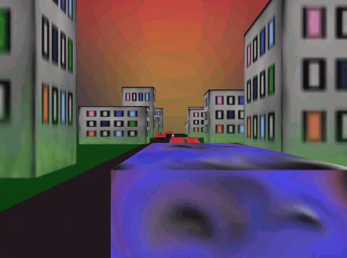
AvatarTest. The viewers avatar is the large cube in the center of the frame
| From AvatarTest.java (see also PlatformTest.java) |
//Create a simple scene and attach it to the virtual universe SimpleUniverse u = new SimpleUniverse();
//Add everything to the scene graphit will now be displayed. BranchGroup scene = sg.createSceneGraph(); u.addBranchGraph(scene);
PlatformGeometry pg = sg.createPlatformGeometry();
//set the just created PlatformGeometry. ViewingPlatform vp = u.getViewingPlatform(); vp.setPlatformGeometry(pg);
//or
Viewer viewer = u.getViewer();
ViewerAvatar viewerAvatar = new ViewerAvatar(); viewerAvatar.addChild( sg.createViewerAvatar() );
viewer.setAvatar( viewerAvatar );
![]()
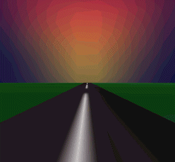
Background geometry is assumed to be positioned at infinite distance, that is, no perspective calculations need to be performed. It is also assumed that it has been tessellated onto a unit sphere. In addition, a background color, an image, and the bounds within which the background is active can be specified. Background geometry is rendered after the background image has been drawn. See figures 6.86.10.
| From AvatarTest.java |
//To set a Background image:
ImageComponent2D image = new TextureLoader(
 "sky.jpg", this).getScaledImage( 1300,1300 );
Background back = new Background( image );
back.setApplicationBounds( getBoundingSphere() );

//To set Background Geometry:
Background back = new Background();
BranchGroup bgGeometry = new BranchGroup();

Appearance ap = new Appearance();
Texture tex = new TextureLoader( "back.jpg", this).getTexture();
ap.setTexture( tex );

Sphere sphere = new Sphere( 1.0f, Primitive.GENERATE_TEXTURE_COORDS |
 Primitive.GENERATE_NORMALS_INWARD, ap );

bgGeometry.addChild( sphere );
back.setGeometry( bgGeometry );
![]()
The foregoing examples have the effect of setting a background image. However, the second approach, using a texture-mapped sphere with the image applied, has an advantage: the texture image is automatically scaled when it is applied to the sphere. In the first example, the background image must be manually scaled to correspond to the size of the rendering window. If the rendering window is resizable, the image must be rescaled or it will merely be painted into the top left corner of the rendering window. Applying the image as a texture may also render considerably faster depending upon your rendering hardware.
In the second example, note that the normal vectors generated for the Sphere must point inward because the viewer is inside the generated Sphere and views the texture applied to the inside of the Sphere. Alternately, the spheres PolygonAttributes can be set to CULL_NONE to render triangles with Normal vectors pointing away from the viewer.
Multiple views can be a useful technique for rendering different views of the created scene. Multiple views are often used in CAD or 3D-editor applications to display the three orthogonal views of an object (side, top, front) as well as an interactive camera view. For complex 3D manipulation, multiple views are sometimes the only way to give the user the required degree of control for interactive object manipulation.
There are a few issues that you should be aware of if you opt to use multiple views.
Java 3D implements Billboard (rotate the object to face the viewer) and LOD (vary the geometry of objects depending on distance from viewer) as operations that directly manipulate the scenegraph. This obviously has implications when there is more than one viewer: if the Billboard Behavior rotates an object to face Viewer1, it cannot simultaneously rotate the object to face Viewer2.
If there is more than one active View, the Billboard and LOD Behaviors will use the orientation and distance information from the first View attached to the live ViewPlatform. This is defined as the primary View for the Behavior and can be returned using the Behavior.getView() method.
The OrientedShape3D class defines a variant of the Shape3D class that is always aligned to face the viewer, irrespective of View.
Sun will be offering more complete support for multiple Views in forthcoming releases, so check the latest details at the Sun Java 3D site.
By now you should have some good ideas as to how you will assemble your application from the components supplied by the Java 3D API, as well as many of the capabilities of the API. The VirtualUniverse class provides flexibility in defining your applications view of your virtual world while the SimpleUniverse class abstracts some of the underlying details and provides a good starting point for simple applications or prototypes. Java 3Ds view model includes built-in support for some powerful features: multiple Locales for very large worlds, rendering to stereoscopic displays, geometry to represent both the view and the viewer, and a physical environment for the view. We have only been able to touch on many of the capabilitiesmany more are introduced in later chapters. If you are interested in using the VirtualUniverse class directly please refer to chapter 17 and the SwingTest example, which builds up the scenegraph from scratch using VirtualUniverse.
In the next chapter, we will start to discuss the important question of the data model you should adopt for your application. Your data model design will ideally be efficient for rendering, while flexible and maintainable enough to satisfy your application and development goals.