14.3 Texture and multiple levels of detail
14.5 Using transparent geometry with transparent texture images
14.6 Animated (video) texture mapping
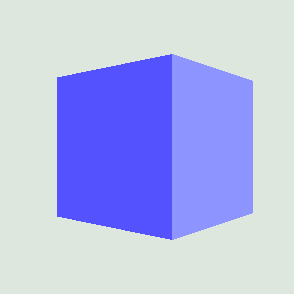
The process of applying a bitmap to geometry is called texture mapping and is often a highly effective way of achieving apparent scene complexity while still using a relatively modest number of vertices. By the end of this chapter, you should be able to generate texture coordinates and apply a texture image to your geometry (e.g., figure 14.1).
If you are familiar with the process of texture mapping and texture coordinates, you may want to skim the first few sections and jump straight to the specifics of the Java 3D implementation.
As colors can only be associated with vertices in the model, if texture mapping was not used, a vertex would have to be located at every significant surface color transition. For highly textured surfaces such as wood or stone, this would quickly dominate the positions of the vertices rather than the geometric shape of the object itself. By applying an image to the geometric model, the apparent complexity of the model is increased while preserving the function of vertices for specifying relative geometry within the model.
Modern 3D computer games have used texture mapping extensively for a number of years, and first-person-perspective games such as Quake by Id software immerses the user in a richly texture-mapped world.
Texture mapping is exactly what it says. As an application developer, you are defining a mapping from 3D coordinates into texture coordinates. Usually this equates to defining a coordinate mapping to go from a vertexs 3D coordinates to a 2D pixel location within an image.
Defining coordinate mappings sounds pretty complicated, but in practice it can be as simple as saying the vertex located at position (1,1,1) should use the pixel located at (20,30) in the image named texture.jpg.
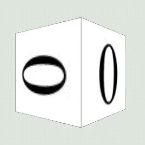
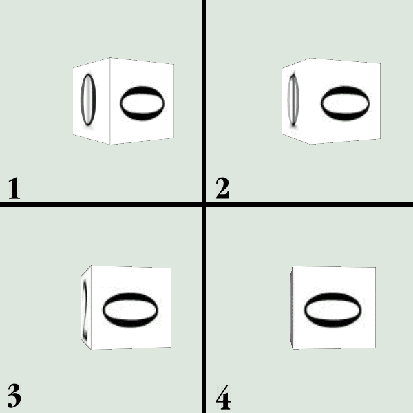
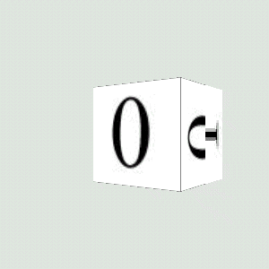
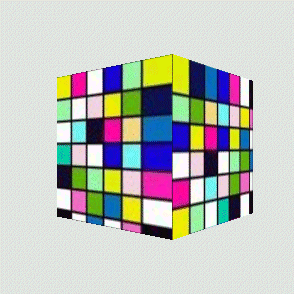
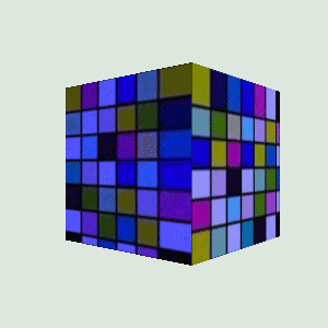
Looking at figure 14.2 it should be obvious that the renderer does some pretty clever stuff when it maps a texture onto a geometric model. The texture used was 64 x 64 pixels in size, but when it was rendered, the faces of each cube were about 200 x 200 pixels. So, the renderer had to resize the texture image on the fly to fit the face of each cube. Even tougher, you can see that what started out as a square texture image turned into a parallelogram as perspective and rotation were applied to the cube.

You should also be able to see that as the texture has been enlarged it has become pixilated. This is because several eventual screen pixels are all mapped to the same pixel within the texture image. This is a common problem with texture mapping and is visible in texture-mapped games such as Quake, as well.
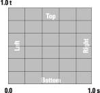
To discuss the details of mapping between 3D vertex coordinates and texture pixels, some terminology must be introduced. Figure 14.3 illustrates texture coordinates. Instead of mapping to pixel locations directly (which would be relative to the size of the texture image), we use texture coordinates. Texture coordinates range from 0.0 to 1.0 in each dimension, regardless of the size of the image. We know therefore that the coordinates s = 0.5, t = 0.25 are always located halfway across the image and three-quarters of the way down from the top of the image. Note that the origin of the texture coordinate system is at the bottom left of the image, in contrast to many windowing systems that define the origin at the top left.
A pixel within an image that is used for texture mapping is often referred to as a texel.
There are essentially two types of texture mapping, static and dynamic. Defining a static mapping is the most commonly used and easiest form of texture mapping and is the subject of section 14.1.1.
Static mapping defines a static relationship between vertex coordinates and texture coordinates. This is usually implemented by simply assigning a texture coordinate to each vertex in the model (table 14.1).
| Vertex 143: |
|---|
| coordinate: 3,6,7 |
| color: red = 184, green = 242, blue = 32 |
| normal vector 0.5, 0.2, -0.3 |
| texture coordinate: 0.3, 0.6 |
Vertex 143 has been assigned a number of attributes: coordinate (position), color, normal vector, and a texture coordinate.
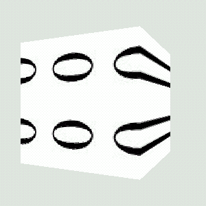
The TextureTest example that follows can be used to experiment with the relationship among images, texture coordinates, and 3D vertex coordinates (figure 14.4).
TextureTest loads the following information from a simple ASCII text file:
For example, the data for the image in figure 14.4 is shown in table 14.2.
| Width 400 Height 400 |
||||||
| Vertex | x | y | x' | y' | tx | ty |
|---|---|---|---|---|---|---|
| 0 | 159 | 99 | 159 | 301 | 0.40 | 0.75 |
| 1 | 125 | 126 | 125 | 274 | 0.31 | 0.69 |
| 2 | 110 | 163 | 110 | 237 | 0.28 | 0.59 |
| 3 | 102 | 243 | 102 | 157 | 0.26 | 0.39 |
| 4 | 118 | 304 | 118 | 96 | 0.30 | 0.24 |
| 5 | 179 | 363 | 179 | 37 | 0.45 | 0.09 |
| 6 | 220 | 364 | 220 | 36 | 0.55 | 0.09 |
| 7 | 264 | 335 | 264 | 65 | 0.66 | 0.16 |
| 8 | 287 | 289 | 287 | 111 | 0.72 | 0.28 |
| 9 | 295 | 204 | 295 | 196 | 0.74 | 0.49 |
| 10 | 279 | 132 | 279 | 268 | 0.70 | 0.67 |
| 11 | 253 | 104 | 253 | 296 | 0.63 | 0.74 |
| 12 | 207 | 95 | 207 | 305 | 0.52 | 0.76 |
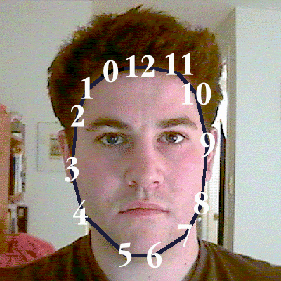
TextureTest example loads an image and a list of texture coordinates and displays a portion of the image in a 3D scene by texture mapping it onto a TriangleArray
daniel.gif		(name of the image file)
5 		(size in the x direction)
1.0 		(y scale factor)
13 		(number of texture coordinates)
0.40	0.75 	(texture coordinate 1, x y)
0.31	0.69
0.28	0.59
0.26	0.39
0.30	0.24
0.45	0.09
0.55	0.09
0.66	0.16
0.72	0.28
0.74	0.49
0.70	0.67
0.63	0.74
0.52	0.76 	(texture coordinate 13, x y)
The Microsoft Excel spread sheet file daniel coords.xls with the TextureTest example contains the formulae necessary for the coordinate transformation (figure 14.5).
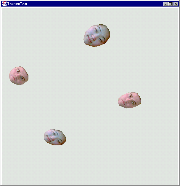
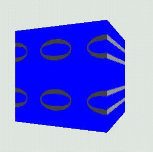
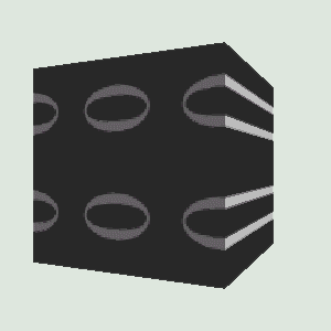
TextureTest example in action. Four texture-mapped TriangleArrays have been created from two sets of texture coordinate data and images. The TriangleArrays are rotated using an Interpolator
| IMPORTANT |
The texture coordinates are specified in counterclockwise order. This is a requirement imposed by the com.sun.j3d.utils.geometry.Triangulator utility, which converts the polygon created from the texture coordinates into a TriangleArray. |
The createTextureGeometry method performs most of the work related to assigning texture coordinates to vertices. There are eight basic steps:
com.sun.j3d.utils.image.TextureLoader class and assign to an Appearance.
//load the texture image and assign to the appearance
TextureLoader texLoader = new TextureLoader( texInfo.m_szImage,
Texture.RGB, this );
Texture tex = texLoader.getTexture();
app.setTexture( tex );GeometryInfo object to store the texture and vertex coordinates (POYGON_ARRAY).
//create a GeometryInfo for the QuadArray that was populated.
GeometryInfo gi = new GeometryInfo( GeometryInfo.POLYGON_ARRAY );GeometryInfo object.
//assign coordinates
gi.setCoordinates( texInfo.m_CoordArray );
gi.setTextureCoordinates( texInfo.m_TexCoordArray );GeometryInfo object.
//use the triangulator utility to triangulate the polygon
int[] stripCountArray = {texInfo.m_CoordArray.length};
int[] countourCountArray = {stripCountArray.length};
gi.setContourCounts( countourCountArray );
gi.setStripCounts( stripCountArray );
Triangulator triangulator = new Triangulator();
triangulator.triangulate( gi );GeometryInfo object.
//generate normal vectors for the triangles,
//not strictly necessary as we are not lighting the scene
//but generally useful
NormalGenerator normalGenerator = new NormalGenerator();
normalGenerator.generateNormals( gi );Shape3D object based on the GeometryInfo object.
//wrap the GeometryArray in a Shape3D and assign appearance
new Shape3D( gi.getGeometryArray(), app );
Please refer to TextureTest.java for the full example. The important methods are listed in full next.
//create a TransformGroup, position it, and add the texture
//geometry as a child node
protected TransformGroup createTextureGroup( String szFile,
 double x, double y, double z, boolean bWireframe )
{
 TransformGroup tg = new TransformGroup();
 Transform3D t3d = new Transform3D();
 t3d.setTranslation( new Vector3d( x,y,z ) );
 tg.setTransform( t3d );

 Shape3D texShape = createTextureGeometry( szFile, bWireframe );

 if( texShape != null )
  tg.addChild( texShape );

 return tg;
}

//return a Shape3D that is a triangulated texture-mapped polygon
//based on the texture coordinates and name of texture image in the
//input file
protected Shape3D createTextureGeometry( String szFile,
 boolean bWireframe )

{
 //load all the texture data from the file and
 //create the geometry coordinates
 TextureGeometryInfo texInfo = createTextureCoordinates( szFile );
 if( texInfo == null )
 {
  System.err.println( "Could not load texture info for file:" +
                      szFile );
  return null;
 }

 //print some stats on the loaded file
 System.out.println( "Loaded File: " + szFile );
 System.out.println( "   Texture image: " + texInfo.m_szImage );
 System.out.println( "   Texture coordinates: " +
                         texInfo.m_TexCoordArray.length );

 //create an Appearance and assign a Material
 Appearance app = new Appearance();

 PolygonAttributes polyAttribs = null;

 //create the PolygonAttributes and attach to the Appearance,
 //note that we use CULL_NONE so that the "rear" side
 //of the geometry is visible with the applied texture image
 if( bWireframe == false )
 {
  polyAttribs = new PolygonAttributes(
    PolygonAttributes.POLYGON_FILL,
    PolygonAttributes.CULL_NONE, 0 );
 }
 else
 {
  polyAttribs = new PolygonAttributes(
    PolygonAttributes.POLYGON_LINE,
    PolygonAttributes.CULL_NONE, 0 );
 }

 app.setPolygonAttributes( polyAttribs );

 //load the texture image and assign to the appearance
 TextureLoader texLoader = new TextureLoader( texInfo.m_szImage,
  Texture.RGB, this );
 Texture tex = texLoader.getTexture();
 app.setTexture( tex );

 //create a GeometryInfo for the QuadArray that was populated.
 GeometryInfo gi = new GeometryInfo( GeometryInfo.POLYGON_ARRAY );
 gi.setCoordinates( texInfo.m_CoordArray );
 gi.setTextureCoordinates( texInfo.m_TexCoordArray );

 //use the triangulator utility to triangulate the polygon
 int[] stripCountArray = {texInfo.m_CoordArray.length};
 int[] countourCountArray = {stripCountArray.length};

 gi.setContourCounts( countourCountArray );
 gi.setStripCounts( stripCountArray );

 Triangulator triangulator = new Triangulator();
 triangulator.triangulate( gi );

 //Generate normal vectors for the triangles, not strictly necessary
 //as we are not lighting the scene, but generally useful.
 NormalGenerator normalGenerator = new NormalGenerator();
  normalGenerator.generateNormals( gi );

 //wrap the GeometryArray in a Shape3D and assign appearance
 return new Shape3D( gi.getGeometryArray(), app );
}

/*
 * Handle the nitty-gritty details of loading the input file
 * and reading (in order):
 * - texture file image name
 * - size of the geometry in the X direction
 * - Y direction scale factor
 * - number of texture coordinates
 * - each texture coordinate (X Y)
 * This could all be easily accomplished using a scenegraph loader,
 * but this simple code is included for reference.
 */
protected TextureGeometryInfo createTextureCoordinates(
 String szFile )

{
 //create a simple wrapper class to package our return values
 TextureGeometryInfo texInfo = new TextureGeometryInfo();

 //allocate a temporary buffer to store the input file
 StringBuffer szBufferData = new StringBuffer();

 float sizeGeometryX = 0;
 float factorY = 1;
 int nNumPoints = 0;
 Point2f boundsPoint = new Point2f();

 try
 {
  //attach a reader to the input file
  FileReader fileIn = new FileReader( szFile );

  int nChar = 0;

  //read the entire file into the StringBuffer
  while( true )
  {
   nChar = fileIn.read();

   //if we have not hit the end of file
   //add the character to the StringBuffer
   if( nChar != -1 )
    szBufferData.append( (char) nChar );
   else
    //hit EOF
    break;
  }

  //create a tokenizer to tokenize the input file at whitespace
  java.util.StringTokenizer tokenizer =
   new java.util.StringTokenizer( szBufferData.toString() );

  //read the name of the texture image
  texInfo.m_szImage = tokenizer.nextToken();

  //read the size of the generated geometry in the X dimension
  sizeGeometryX = Float.parseFloat( tokenizer.nextToken() );

  //read the Y scale factor
  factorY = Float.parseFloat( tokenizer.nextToken() );

  //read the number of texture coordinates
  nNumPoints = Integer.parseInt( tokenizer.nextToken() );

  //read each texture coordinate
  texInfo.m_TexCoordArray = new Point2f[nNumPoints];
  Point2f texPoint2f = null;

  for( int n = 0; n < nNumPoints; n++ )
  {
   texPoint2f = new Point2f(  Float.parseFloat(
            tokenizer.nextToken() ),
            Float.parseFloat( tokenizer.nextToken() ) );

   texInfo.m_TexCoordArray[n] = texPoint2f;

   //keep an eye on the extents of the texture coordinates
   // so we can automatically center the geometry
   if( n == 0 || texPoint2f.x > boundsPoint.x )
    boundsPoint.x = texPoint2f.x;

   if( n == 0 || texPoint2f.y > boundsPoint.y )
    boundsPoint.y = texPoint2f.y;
  }
 }
 catch( Exception e )
 {
  System.err.println( e.toString() );
  return null;
 }

 //build the array of coordinates
 texInfo.m_CoordArray = new Point3f[nNumPoints];

 for( int n = 0; n < nNumPoints; n++ )
 {
   //scale and center the geometry based on the texture coordinates
texInfo.m_CoordArray[n] = new Point3f( sizeGeometryX  *
 texInfo.m_TexCoordArray[n].x - boundsPoint.x/2),
 factorY * sizeGeometryX *
 (texInfo.m_TexCoordArray[n].y - boundsPoint.y/2), 0 );
 }

 return texInfo;
}
As the TextureTest example illustrates, using a static mapping from vertex coordinates is relatively straightforward. Texture coordinates are assigned to each vertex, much like vertex coordinates or per-vertex colors. The renderer will take care of all the messy details of interpolating the texture image between projected vertex coordinates using projection and sampling algorithms.
Texture coordinates themselves are usually manually calculated or are the product of an automated texture-mapping process (such as 3D model capture or model editor).
Note that although we have called this section static mapping, there is nothing to prevent you from modifying the texture coordinates within a GeometryArray at runtime. Very interesting dynamic effects can be achieved through reassigning texture coordinates.
Care must be taken to ensure that texture images do not become too pixilated as they become enlarged and stretched by the sampling algorithm. The MIPMAP technique covered in detail in Section 14.3.4 is useful in this regard in that different sizes of different texture images can be specified.
Needless to say, texture images consume memory, and using large 24-bit texture images is an easy way to place a heavy strain on the renderer and push up total memory footprint. Of course, the larger the texture image, the less susceptible it is to becoming pixilated so a comfortable balance must be found between rendering quality, rendering speed, and memory footprint. You should also be very aware that different 3D rendering hardware performs texture mapping in hardware only if the texture image falls within certain criteria. Modern 3D rendering cards typically have 16 MB or more of texture memory, and 64 MB is now not uncommon. Most rendering hardware will render texture images of up to 512 x 512 pixels. You should consult the documentation for the 3D rendering cards that your application considers important.
In contrast to a hard-coded static mapping between vertex coordinates and texture coordinates, dynamic texture mapping enables the application developer to define a mapping that is resolved by the renderer at runtime. Dynamic mapping is fairly unusual but is very useful for certain scientific visualization applicationswhere the position of a vertex in 3D space should correlate with its texture coordinate.
Rather than having to manually update the texture coordinate whenever a vertex moves, the application developer defines a series of planes that the renderer uses to calculate a texture coordinate.
The TexCoordTest example application explores the three texture coordinate generation options in Java 3D. These are TexCoordGeneration.EYE_LINEAR, TexCoordGeneration.OBJECT_LINEAR, and TexCoordGeneration.SPHERE_MAP (figures 14.614.11). Each will be described in turn in the sections that follow.
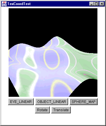
TexCoordTest example application in action. The vertices in the undulating landscape do not have assigned texture coordinates, but rather a TexCoordGeneration object is used to calculate texture coordinates dynamically
The OBJECT_LINEAR texture coordinate generation mode calculates texture coordinates based on the relative positions of vertices. The TexCoordTest example creates a simulated landscape that has contours automatically mapped onto the landscape Everything above the y = 0 plane is texture-mapped green, while everything below is texture-mapped blue.
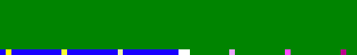
Figure 14.7 illustrates the texture image used in the TexCoordTest example for dynamic texture mapping. The texture image is 64 x 64 pixels and merely contains a single row of pixels that is of interestthe rest of the image is ignored. The bottom row of the image (t = 0) defines the colors to be dynamically applied to the landscape. The midpoint of the row (s = 0.5) defines the elevation = 0 (sea level) contour, while everything to the left of the midpoint is used for elevations below sea level, and everything to the right is used for elevations above sea level. Different colored pixels for contours are evenly spaced from the midpoint.
TexCoordTest example application
To map contours onto the landscape we merely need to define a mapping from the y coordinate of the landscape to the s coordinate of the texture image. That is, we are defining a 1D-to-1D mapping from vertex coordinates to texture coordinates.
A vertexs position is defined using three dimensions (x,y,z), while a texture coordinate can potentially be expressed in three dimensions (although typically only s and t are used).
We define a plane for each of the texture coordinates (s, t, and sometimes r). The s texture coordinate is given by a vertexs position relative to the s plane, the t coordinate is given by a vertexs position relative to the t plane, and so on. Planes are defined by specifying the direction of the vector perpendicular (normal) to the plane.
For example, to create our mapping from y vertex coordinate to s texture coordinate:
TexCoordGeneration texGen =
 new TexCoordGeneration( TexCoordGeneration.OBJECT_LINEAR,
                         TexCoordGeneration.TEXTURE_COORDINATE_2,
                         new Vector4f( 0,
                                       (float)
                                       (1.0/(2 * yMaxHeight)),
                                       0,
                                       0.5f ),
                         new Vector4f( 0,0,0,0 ),
                         new Vector4f( 0,0,0,0 ) );
The parameters to the TexCoordGeneration constructor do the following:
OBJECT_LINEAR.
The mapping from vertex coordinates to s coordinates we defined was:
(0, (float) (1.0/ (2 * yMaxHeight)), 0, 0.5f)
This equates to:
s texture coordinate = (0.0 * vertex x) + (1.0/ 2 * yMaxHeight * vertex y) + (0.0 * vertex z) + 0.5;
OBJECT_LINEAR texture coordinate generation
That is, the t texture coordinate is equal to a scaled version of the y vertex coordinate plus an offset of 0.5. We use an offset of 0.5 because we defined the midpoint of the texture image as the elevation = 0 contour.
From the equation you can see that:
Vertex y = yMaxHeight, s = 1.0
Vertex y = 0.0, s = 0.5
Vertex y = yMaxHeight, s = 0.0
That is, we have successfully defined a mapping from vertex y coordinate in the range ± yMaxHeight to s texture coordinates in the range 0.0 to 1.0. The texture coordinate is independent of a vertexs x and z coordinates.
Using theOBJECT_LINEAR mode, the landscape has texture coordinates automatically calculated, coloring areas above sea level green (light gray) and areas below sea level blue (dark gray). As the landscape as a whole is rotated and translated, the texture coordinates are unaffected. The vertex coordinates in the local coordinate system of the landscape are unchanged, despite the origin of the landscapes coordinate being shifted.
The EYE_LINEAR texture coordinate generation mode is very similar to the OBJECT_LINEAR mode with one important difference. The positions of vertices in their local coordinate system are no longer used; rather the positions of vertices in the world coordinate system are used instead. This has major consequencesas the landscape is moved within the VirtualUniverse, the texture coordinates of the vertices within the landscape are recomputed, for example, in the TexCoordTest example, by simply modifying the construction of the TexCoordGeneration object to be:
TexCoordGeneration texGen =
new TexCoordGeneration( TexCoordGeneration.EYE_LINEAR,
TexCoordGeneration.TEXTURE_COORDINATE_2,
new Vector4f( 0,
(float)
(1.0/(2 * yMaxHeight)),
0,
0.5f ),
new Vector4f( 0,0,0,0 ),
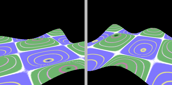
new Vector4f( 0,0,0,0 ) );We define a VirtualUniverse where the texture coordinate of the landscape is calculated from the y coordinate of the landscape in the VirtualUniverses coordinate system. In essence we have defined a band of texture coordinates (color) that ranges from yMaxHeight to +yMaxHeight. When the landscape falls inside this range, it will have a texture coordinate applied to it.
In mathematical terms, this is equivalent to multiplying each vertex coordinate by the result of calling Shape3D.getLocalToVworld before computing the texture coordinate using:
s texture coordinate = (0.0 * vertex x) + (1.0/ 2 * yMaxHeight * vertex y) + (0.0 * vertex z) + 0.5;
Using the EYE_LINEAR mode allows you to define a field of texture coordinates that can produce dynamic contour lines on moving objects.
EYE_LINEAR texture coordinate generation. As the landscape is translated upward in the y axis, the texture coordinates change, resulting in a different frame. In the left-hand frame, only the peaks of the landscape are above the y = 0 plane; the rest of the landscape is either texture mapped with the water section of the texture image or does not have any texture applied since the calculated texture coordinate is less than 0.0. In the right-hand frame, most of the landscape is above the y = 0 plane, and only the deepest hollows in the landscape are textured using the water section of the texture image
The SPHERE_MAP mode is very different from the OBJECT_LINEAR or EYE_LINEAR modes in that it always generates 2D (s,t) texture coordinates irrespective of any mapping planes passed to the TexCoordGeneration constructor.
SPHERE_MAP mode calculates texture coordinates based on the vector passing from the origin (in world coordinates) to a vertex. It creates a mapping that essentially paints an environment map onto the face of an object. Imagine that the object was a reflective sphere positioned in the center of a room. If the SPHERE_MAP texture coordinate generation mode was used, the sphere would appear to reflex the items within the room. By precomputing a spherical texture map using a ray-tracing program and using the SPHERE_MAP texture mode, a photorealistic reflective object can be created.
| NOTE |
Please refer to the OpenGL 1.1 Specification for the mathematical details of how the texture coordinates are calculated from the vector passing from the origin to each vertex. |
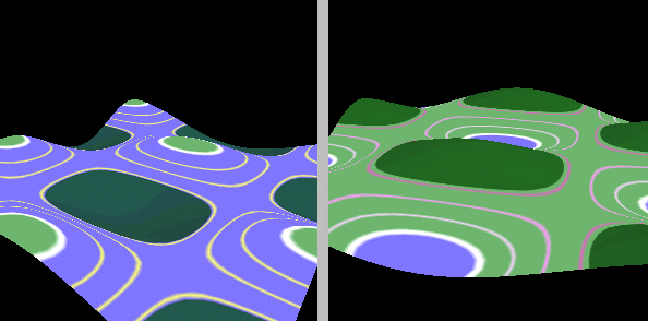
Because the SPHERE_MAP mode always generates both s and t coordinates, we have to create a texture image to achieve the effect in figure 14.10. This texture image is shown in figure 14.11. However, because both the TexCoordTest example in EYE_LINEAR and OBJECT_LINEAR modes only use the t = 0 row of the image, their results are unchanged.

SPHERE_MAP texture coordinate generation. Instead of the texture image being used to denote contour lines on the landscape, the landscape can now be considered to be a reflective surface within a spherical room that has the texture image applied as wallpaper to its inner walls
SPHERE_MAP texture coordinate generation
Dynamic texture mapping is a very powerful mechanism for applications that can define a relatively simple mathematical relationship between vertex and texture coordinates. The SPHERE_MAP mode is useful for creating some special effects for the objects within your scene.
All three texture generation options can be confusing and are certainly more complex than simply using assigned texture coordinates. I suggest you experiment with the TexCoordTest example, edit the texture images, and change the mapping planes until you are comfortable with the techniques and have an intuitive feel for the mathematics behind the texture coordinate generation options.
The previous section included some hand waving on the subject of 3D texture coordinates. The 3D texture coordinates are fairly unusual and are at present supported by Java 3D only on the Solaris platform. Instead of a 2D texture image being applied to a surface, a 3D object can appear to have been carved from a 3D texture. Some textures are inherently 3D and are easiest to specify procedurally (such as the grain in wood). Using a 3D texture image defines a color (potentially with an alpha value) for each x,y,z location. Texels, instead of being 2D squares, are now 3D cubes within the three dimensions of the texture image (s,t,r).
For example, if a 2D wood grain texture were applied to the faces of a cube, the grain lines would not match up at the edges of the faces of the cube. By using a 3D texture image, the grain lines will appear to run through the cube in a realistic manner.
Similarly, in a 3D visualization application, such as MRI scanning, a 3D texture image might be used to represent the color of each voxel within a volume rendering. This might be used as a cheat to create a relatively coarse voxel resolution and apply a high-resolution 3D texture image to trade off accuracy against interactive performance.
java.lang.Object
  |
  +--javax.media.j3d.SceneGraphObject
        |
        +--javax.media.j3d.NodeComponent
              |
              +--javax.media.j3d.Texture
Capability Bits (OpenGL Reference: glTexImage2D, glTexParameter):
BOUNDARY_COLOR
ENABLE
FILTER
IMAGE
MIPMAP_MODE
Texture is an abstract class and hence cannot be instantiated. The two derived classes Texture2D or Texture3D (used with 2D or 3D texture coordinates respectively) should be instantiated instead. Texture-derived objects are usually not created directly but are returned by the getTexture method of the TextureLoader utility class. See section 14.3.3 for more details.
CLAMP and the MinFilter was set to NICEST
Setting the boundary mode to Texture.WRAP allows texture coordinates greater than 1 to be used. The texture image will be repeated (tiled) along each axis (s, t, or r) that has the WRAP boundary mode. If CLAMP is used, texture coordinates outside the 0 to 1 range will be ignored. See figure 14.12 for an example of how CLAMP and MinFilter can be used.
Note that the texture image can be flipped in each axis by using the WRAP attribute and a texture coordinate of 1.
Setting the image within the Texture object is achieved using the setImage method. The TextureLoader utility class is usually used to create the Texture with an image applied:
| From TextureTest.java |
//Create TextureLoader and initialize it with an image file name
//and a mode
TextureLoader texLoader = new TextureLoader( texInfo.m_szImage,
 Texture.RGB, this );

//Extract a Texture object from the loader
Texture tex = texLoader.getTexture();

//Assign the Texture to the Appearance
Appearance app = new Appearance();
app.setTexture( tex );![]()
The advantages of using the TextureLoader class are:
Texture object, either Texture2D or Texture3D
If an ImageComponent2D or ImageComponent3D is passed to Texture.setImage directly and the TextureLoader class is not used, the application developer is responsible for ensuring that the images are a power of 2 (1, 2, 4, 8
) in both width and height. This is a requirement imposed by the underlying graphics API that is optimized to rescale images of this size.
One of the common problems of texture mapping is that the texture images become pixilated as resampling enlarges them. The quick fix to this is to ensure that all your texture images are large enough so that they can never become overly magnified.
Imagine a cube in your scene with a texture image applied to one face. If the cubes texture image is 64 x 64 pixels and the cube is very close to the viewer, it may end up taking up 300 x 300 pixels on the screen. A texture image that has been magnified by a factor of 5 is obviously not going to look very goodregardless of the sophistication of the sampling algorithm employed by the graphics hardware. A solution to this problem would be to assign a 256 x 256 pixel texture image to each face of the cube.
However, we are now using 16 times as much texture memory. To complicate matters, most of the time the cube is probably considerably further away from the viewer, and the graphics API will have to work hard to sample the 256 x 256 size image down to an appropriate size based on the cubes distance.
What we need, and what MIPMAPs provide, is the ability to specify multiple texture images. The graphics API will select the most appropriate one based on the size of the surface it is trying to render. We pay the penalty of storing multiple texture imageswhich is incidentally very small compared to storing the largest texture image.
For example,
64 x 64 = 4096
32 x 32 = 1024
16 x 16 = 256
8 x 8 = 64
4 x 4 = 16
2 x 2 = 4
1 x 1 = 1
The cost of storing the 64 x 64 pixel image is proportional to 4096, while the cost of storing all the other images is proportional to 1365. So using MIPMAPs will improve performance for a very low memory penalty.
To use MIPMAPs you must specify all the texture images from your maximum size (which must be a power of 2, right down to the 1 x 1 image). So, if our largest texture image is 64 x 64 pixels, we require seven texture images. Usually, of course, the texture images will be increasingly low resolution images of the same feature. Texture images can be easily preprocessed using the resampling features of a bitmap editor such as PhotoShop (Adobe) or PaintShop Pro (JASC).
In figure 14.13, the AppearanceTest example uses texture images that are different so that the texture image that was chosen by the graphics API is apparent.
AppearanceTest example to illustrate Java 3D MIPMAP support64 x 64 pixels down to 1 x 1 pixels
The individual texture images can be assigned to a Texture object as follows. Note that Texture.MULTI_LEVEL_MIPMAP was used to activate MIPMAP support.
| From AppearanceTest.java |
//Create a texture loader and load the largest image (64x64-pixels)
TextureLoader texLoader =
  new TextureLoader( "texture00.jpg", m_Component );

//Retrieve the ImageComponent from the TextureLoader
ImageComponent2D image = texLoader.getImage();

//Create a MULTI_LEVEL_MIPMAP mode Texture2D object
//based on the size of the largest image
Texture2D tex2D =
  new Texture2D( Texture.MULTI_LEVEL_MIPMAP, Texture.RGBA,
  image.getWidth(), image.getHeight() );

//Now load each of the 7 images and assign to the Texture2D
for( int n = 0; n <= 6; n++ )
{
 texLoader = new TextureLoader(
  "texture0" + n + ".jpg", m_Component );
 tex2D.setImage( n, texLoader.getImage() );
}

//assign the Texture2D to the appearance
m_Appearance.setTexture( m_Texture );![]()
Once the graphics API has multiple texture images to choose from, it needs some criteria to decide which texture image to display. The graphics API obviously uses the texture image that is easiest to resample to the desired size; however, some more advanced options are also available. These are controlled by the setMinFilter and setMagFilter methods (table 14.3).
| MinFilter Option | Effect |
|---|---|
| FASTEST | Equivalent to BASE_LEVEL_POINT |
| NICEST | Equivalent to MULTI_LEVEL_LINEAR |
| BASE_LEVEL_POINT | Finds nearest texel in the level 0 texture map |
| BASE_LEVEL_LINEAR | Performs bilinear interpolation on the four nearest texels in the level 0 texture map |
| MULTI_LEVEL_POINT | Selects the nearest texel in the nearest MIPMAP |
| MULTI_LEVEL_LINEAR | Performs trilinear interpolation of texels between four texels each from the two nearest MIPMAP levels |
| FASTEST | Equivalent to BASE_LEVEL_POINT |
| NICEST | Equivalent to BASE_LEVEL_LINEAR |
| BASE_LEVEL_POINT | Selects the nearest texel in the level 0 texture map |
| BASE_LEVEL_LINEAR | Performs a bilinear interpolation on the four nearest texels in the level 0 texture map |
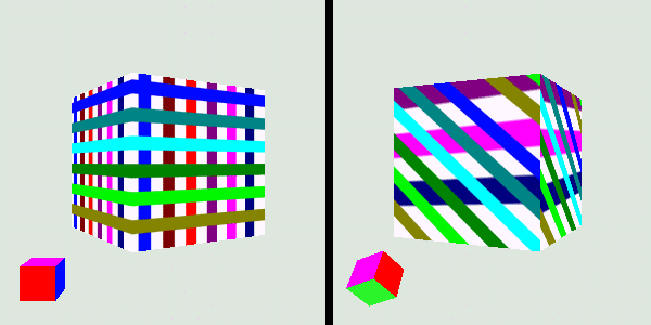
Figure 14.14 illustrates how complex blending of the MIPMAP texture images can be achieved. In frame 1 the left-hand face of the cube is dominated by the level 0 texture image, which progressively passes through the 1, 2, and 3 texture images as the size of the surface is reduced through rotation (frames 2 through 4). The blending of multiple texture images obviously requires more work on the part of the graphics API.
AppearanceTest example illustrate how multiple texture images are blended when the MULTI_LEVEL_LINEAR MinFilter and BASE_LEVEL_LINEAR MagFilter are used
In contrast, when the MULTI_LEVEL_POINT mode is used, the texture images are not blended but rather different texture images are chosen for different pixels within the surface, based on the position of the pixel within the surface (figure 14.15). This is the fastest way for the graphics API to support multiple levels of detail texture images.
MULTI_LEVEL_POINT MinFilter mode is used, texture images are not blended, but rather separate images are used for different portions of the surface. The right-hand face of the cube uses the level 0 texture image at the front of the face and the level 1 texture image at the rear of the cube
MIPMAPs are a relatively easy way to improve the appearance of the texture mapping in your application. Experiment with the AppearanceTest example application to strike a good balance between texture mapping appearance and performance. Most modern graphics hardware has built-in support for MIPMAPs, although the rendering quality varies greatly depending on hardware.
java.lang.Object
  |
  +--javax.media.j3d.SceneGraphObject
        |
        +--javax.media.j3d.NodeComponent
              |
              +--javax.media.j3d.TextureAttributes
Capability Bits (OpenGL Reference: glTexEnv):
BLEND_COLOR
MODE
TRANSFORM
The TextureAttributes appearance component controls three parameters related to texture mapping: the color used for texture blending, how the texture image is combined with the material colors (MODE), and a geometric transform that is applied to the texture image during texture mapping.
The blend color is only used when the TextureAttributes.BLEND mode is selected. Figures 14.1614.18 are relatively self-explanatory and illustrate how the blend color affects the eventual applied texture.
TextureAttributes assigned
See figures 14.1914.23 and table 14.4 for descriptions of the four modes in which a texture image can be applied to a surface:
| Mode | Effect |
|---|---|
| DECAL | Color value is the product of the surface color and 1 alpha value for the surface plus texture color times texture alpha. The texture is applied to the surface in proportion to the alpha components of both the texture and the surface. The texture must either be in RGB or RGBA format. |
| MODULATE | Color value is the product of the color values of the texture and the surface color. If MODULATE is used with dark textures the surface may end up black. |
| BLEND | The color values on the surface are modulated by the color values of the texture and biased by the blend color. |
| REPLACE | Color value is simply the texture color. |

Refer to the Java 3D API Specification for more details on the texture mapping equations.
A rotational transformation can also be applied to the texture image prior to texture mapping. This is a fairly unusual operation but might prove useful for specialized operations or to implement special effects. The TextureTransformTest example creates a texture mapped Box and allows the user to interactively rotate the texture applied to the Box using the mouse (figure 14.24).
Note that only the rotational components of the Transform3D appear to be used.
| From TextureTransformTest.java |
//create a Box with an applied Texture image
//and a RotationInterpolator to rotate the box
protected BranchGroup createSceneBranchGroup()
{
 BranchGroup objRoot = super.createSceneBranchGroup();

 TransformGroup objTrans = new TransformGroup();
 objTrans.setCapability(TransformGroup.ALLOW_TRANSFORM_WRITE);
 objTrans.setCapability(TransformGroup.ALLOW_TRANSFORM_READ);

 Transform3D yAxis = new Transform3D();
 Alpha rotationAlpha = new Alpha(-1, Alpha.INCREASING_ENABLE,
  0, 0,
  4000, 0, 0,
  0, 0, 0);

 //create the rotation interpolator to rotate the scene
 RotationInterpolator rotator =
  new RotationInterpolator(rotationAlpha,
   objTrans, yAxis, 0.0f, (float) Math.PI*2.0f);
 rotator.setSchedulingBounds( createApplicationBounds() );
 objTrans.addChild(rotator);

 //create the box
 final int nScale = 50;
 Appearance app = new Appearance();
 Box box = new Box( nScale, nScale, nScale,
                    Primitive.GENERATE_NORMALS |
                    Primitive.GENERATE_TEXTURE_COORDS, app );

 //load the texture image
 TextureLoader texLoader = new TextureLoader( "texture.gif", this );
 app.setTexture( texLoader.getTexture() );

 //set the texture attributes and ensure we can write
 //to the Transform for the texture attributes
 m_TextureAttributes = new TextureAttributes();
 m_TextureAttributes.setCapability(
   TextureAttributes.ALLOW_TRANSFORM_WRITE );
 app.setTextureAttributes( m_TextureAttributes );

 //connect all the elements
 objTrans.addChild( box );
 objRoot.addChild( objTrans );
 objRoot.addChild( createRotator() );

 return objRoot;
}

//private TransformGroup createRotator()
{
 //create a ColorCube to illustrate the current rotation
 TransformGroup transTg = new TransformGroup();
 Transform3D t3d = new Transform3D();
 t3d.setTranslation( new Vector3d( -70, -70, 50 ) );
 transTg.setTransform( t3d );

 TransformGroup subTg = new TransformGroup();
 subTg.setCapability(TransformGroup.ALLOW_TRANSFORM_WRITE);

 subTg.addChild( new ColorCube(10.0) );

 //attach a MouseRotate behavior so we can rotate
 //the color cube with the left mouse button
 MouseRotate mouseRot = new MouseRotate( subTg );
 subTg.addChild( mouseRot );

//assign a transformChanged callback, because we want
//to be notified whenever the rotation of the ColorCube changed
//("this" implements MouseBehaviorCallback );

 mouseRot.setupCallback( this );
 mouseRot.setSchedulingBounds( getApplicationBounds() );

 transTg.addChild( subTg );

 return transTg;
}

//this is a callback method that the MouseRotate behavior calls
//when its Transform3D has been modified (by the user)
public void transformChanged(int type, Transform3D transform)
{
 //update the rotation of the TextureAttributes
 m_TextureAttributes.setTextureTransform( transform );
}![]()
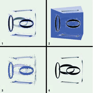
The Texture class allows texture images to have red, green, blue, and alpha (transparency) channels through the RGBA mode. Appearances (and hence geometry) can also have transparency information, either through per-vertex COLOR_4 colors, or through the TransparencyAtttributes NodeComponent. Figures 14.25 14.27 illustrate what happens when partially transparent images are applied to partially transparent Shape3Ds.
The easiest way to use transparent images is to use the GIF image format, which can include a transparent color. Most bitmap editors, such as JASC PaintShop Pro or Adobe Photoshop, can save GIF images with a transparent color.
Figures 14.2514.27 were generated using the AppearanceTest example application. The Box had the appearance attributes shown on table 14.5.
| Transparency: 0.5, NICEST |
| Material: Ambient = white, Diffuse = white, Emissive = blue, Specular = black, Shininess = 1 |
| Texture: MagFilter = BASE_LEVEL_LINEAR, MinFilter = MULTI_LEVEL_LINEAR |
| MIPMAPs were enabled. |
| The front face (smaller) of the cube uses per-vertex colors with transparency and hence is unaffected by the overall TransparencyAttributes of the Boxs Appearance. |
Figure 14.25 is provided for contrast; it uses the opaque texture image (texture0n.jpg).
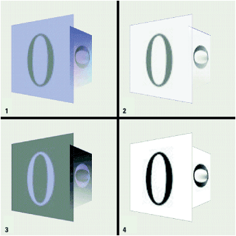
Figure 14.26 uses a transparent version (texture2n.gif) of the original texture image. The white background of the texture image has been marked as a transparent color in the GIF image.
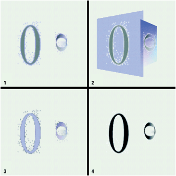
Figure 14.27 uses the transparent texture image but also disables back-face removal using PolygonAttributes.CULL_NONE. Frame 2 (DECAL) suffered from continuous redraw because the back faces were redrawn over the front faces, and then the back faces were redrawn.
Many recent computer games use animated texture maps, for example, to map an MPEG video clip onto the face of a cube. 3D accelerator hardware is also starting to support video textures. Drawing animated textures is at present problematic in Java 3D because, although you can draw into an ImageComponent and use it as a texture image, the ImageComponent is copied into texture memory. Java 3D 1.2 should go some way to addressing this issue, but performance problems are likely to remain an issue for some time.
For very simple texture animations (a few frames), each frame of the animation can be pasted (either at runtime or as a preprocess) into a composite texture image. At runtime the texture coordinates of vertices can be modified to cycle through the various frames of the animation.
This chapter has given you a taste of the power of texture mapping and the important role it plays in most 3D applications, be they educational, scientific, or entertainment. Texture mapping requires a little more work from the application developer, in terms of learning new terminology and methods, but the end results justify the extra development time.
Clever use of lighting and texture mapping sets the great, visually immersive 3D applications apart from flat, uninspiring computer graphics.